


Integrated GSM and GPS system OBD-II to enhance remote vehicle condition monitoring
2021-06-27
The concept of an on-board diagnostic (OBD) system was first introduced by General Motors (GM) in 1982 to monitor emissions control systems. Once a fault is detected, the OBD system will light an indicator on the dashboard to inform the driver and record a code in the onboard computer, commonly referred to as the Engine Control Unit (ECU) or Engine Control Module (ECM). Obtained through the corresponding device for troubleshooting.
This article refers to the address: http://
The California Air Resources Board (CARB) adopted the standards set by the Society of Automotive Engineers (SAE) in 1985, requiring all vehicles sold in California to have basic OBD functionality since 1988. After that, the US Environmental Protection Agency (EPA) required that all new cars sold in the United States must meet the relevant OBD technical requirements since 1991. This is OBD-I.
The Society of Automotive Engineers standardizes technical details such as diagnostic interfaces and communication methods. On the basis of this, OBD-I developed the second generation OBD, namely OBD-II. The US Environmental Protection Agency adopted new technical standards and revised the cleaning in 1990. The Clear Air Act requires that all new vehicles sold in the US market must comply with the technical requirements defined by OBD-II as of January 1, 1996.
In 2001, the European Union also required European cars produced by automakers in Europe to be equipped with the European On-board Diagnosis System (EOBD) system.
In April 2005, the State Environmental Protection Administration of China and the General Administration of Quality Supervision, Inspection and Quarantine jointly promulgated GB18352.3-2005, which is the emission limit and measurement method for light vehicle pollutants, referred to as “Country III, IV”. According to the requirements of the National III, starting from July 1, 2008, the first type of gasoline vehicles (the M1 vehicles with a total number of seats not exceeding six and the maximum total mass not exceeding 2,500 kg) must be forced to install the OBD system and be used. Synchronous execution in the vehicle compliance check.
OBD-II technical requirements cover four major areas
According to the requirements of GB 18352.3, external diagnostic equipment in communication with the vehicle OBD-II system must comply with ISO 15031-4 "Road vehicles - Communication between external diagnostic equipment associated with emissions - Part 3: Requirements for external fault diagnostic equipment "Requirements." These requirements mainly include four aspects of unified diagnostic connector, compatible communication protocol, standard fault code and diagnostic service range, which will be explained below.
Different vehicle diagnostic connectors must be unified
The connector between the OBD universal fault diagnostic device and the vehicle must use a unified diagnostic connector. For the physical interface specification, refer to the J1962 protocol. The pin configuration definition is shown in Figure 1. The undefined pins can be reserved for the diagnostic device. .
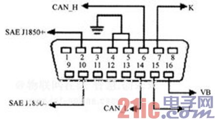
Figure 1: Unified Diagnostic Connector Pin Configuration
External diagnostic equipment must support all communication protocols
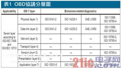
The protocols available for communication between the OBD Universal Fault Diagnosis System and the vehicle are ISO 9141, SAE J1850 41, 6Kb/s PWM (Pulse Width Modulation), SAEJ185010, 4Kb/s VPW (Variable Pulse Width) / ISO 14230 (KW) 2000) / ISO 15765-4 (CAN) and SAE J1939-73 (CAN). According to SAE J1978 or ISO 15031-5, only one communication protocol is allowed for any vehicle. However, for OBD systems compatible with various models, external diagnostic equipment must support all of the above communication protocol specifications. The specific protocol layering is shown in Table 1.
The ISO 15031-5 specification covers the nine service modes available for external diagnostic equipment. The first mode is to read current power system diagnostic data in order to obtain relevant data on the vehicle, such as intake system related parameters, exhaust system related parameters, Engine speed, vehicle speed, fuel type, engine operating conditions, engine turn-on time, control module voltage, and fault codes. The second service mode is to read the system freeze frame, which collects freeze frames associated with power system emissions at the time of the failure and other system freeze frames for the manufacturer's special needs. The third mode is to read the diagnostic trouble code and obtain the general diagnostic trouble code for each system of the vehicle from an external diagnostic device.
The fourth mode is to clear/reset the emission related diagnostic information, which is a method for the external diagnostic device to provide information for clearing the ECU fault diagnosis information of the vehicle. These fault diagnosis information includes the number of diagnostic trouble codes, diagnostic trouble codes, fault codes of frozen frame data, freeze frame data, status of system monitoring test, vehicle monitoring test results, mileage traveled when MIL starts, and preheated after DTC clearing. The number of times, the mileage after the DTC is cleared, the time the engine is running when the MIL starts, the time after the diagnosis of the fault code is cleared, and other record information defined by other manufacturers.
The fifth mode is the readable oxygen sensor monitoring test results. The sixth mode is to read the monitoring test results of the special monitoring system on the vehicle. This mode is that the external diagnostic equipment obtains non-continuous monitoring or continuous monitoring results of special components or other components of the system. The seventh mode of reading the emission-related diagnostic trouble code detected during the current or most recent driving means that the external diagnostic device obtains a diagnostic trouble code detected during the current or most recent driving. This code indicates the effectiveness of the test service by a service technician after a vehicle repair or clearing diagnostic information through a single driving cycle.
The eighth diagnostic equipment service is the control of the on-board system, test or component that is designed to allow the external diagnostic equipment to control the operation of the on-board system, test or component. The ninth mode is to read the vehicle information so that the external diagnostic device can request vehicle information indicating the vehicle, such as the vehicle identity identifier and the calibration ID.
Diagnostic fault code consists of two bytes
The specification of the fault code in ISO 15031-6 states that the OBD diagnostic trouble code (DTC) read by the fault diagnostic device consists of two bytes, which are displayed as 1 letter + 1 digit decimal number + 3 digits ten. The standard display mode of hexadecimal numbers is displayed.
OBD-II still has challenges to be solved
Since the OBD-II data is acquired by the external diagnostic device to send the data request to the OBD diagnostic interface, and then the result is given by the relevant control unit, the abnormality generated by the OBD data is acquired during the driving process of the vehicle, and the impact on the driving safety is It also concerns factors that need to be considered in product design. At the same time, since the original intention of OBD is only to detect exhaust emissions, the OBD diagnostic interface itself can provide limited vehicle data.
Although OBD-II can diagnose emissions-related faults, it cannot guarantee that drivers will accept MIL warnings, repair vehicles in time, or increase the difficulty of remote assistance due to lack of relevant data. For this reason, the transmission of vehicle condition information by wireless communication, including the fault code, will become a new feature of the new generation OBD system.
OBD-III derived richer applications
The future trend of OBD-III is to combine the existing in-vehicle GSM/3G and Global Positioning System (GPS) platforms to create a more versatile automotive networking information platform (Figure 2). For example, in line with the OBD-III automotive networking information platform, the traffic control center or the fleet management center can not only detect the driving standard of the vehicle, but also detect the vehicle condition information in real time, such as whether the vehicle emissions exceed the standard. .
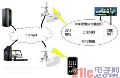
Figure 2: Remote OBD System
In the integrated system, in addition to the microcontroller (MCU) main control terminal to complete the various tasks of the original car GPS, the function of the microcontroller to send data request command and parsing command reply to the body OBD interface, and analyze the result at the same time. , to determine whether to send relevant alerts. The server side searches for the fault code in the corresponding database according to the corresponding alarm information, and displays specific fault information. At the same time, the server can also perform relevant application processing on the closed data collected by the OBD interface, such as analysis of vehicle driving habits, analysis of vehicle fuel consumption, and recording and processing of vehicle maintenance information.
After the original GSM/3G and GPS platform is integrated with OBD-II, the remote communication can not only realize various alarms and remote monitoring of the GPS platform, but also realize real-time alarm and remote monitoring of vehicle faults.
We make OBD connector with terminal by ourselves, soldering type and crimping type are both available. Also 12V and 24V type. OBD1, OB2, J1939, J1708, J1962, etc. Also molded by different type, straight type or right-angle type. The OBD connector cables used for Audi, Honda, Toyota, BWM, etc. We have wide range of materials source , also we can support customers to make a customized one to replace the original ones.
Sae J1708 Connector, Sae J1939 Connector, OBD2 Diagnostic Connectors, Diagnostic Connector, Deutsch Diagnostic Connector
OBD2 Vehicle GPS Tracker,GPS Vehicle Tracker,GPS Motorcycle Tracker Co., Ltd. http://www.oemwireharness.com